Another one of these? Really? #
Yes. I love my Ambilight setup on my TV, and when I was originally doing this had some trouble oweing to different information here and there, so decided to do my own blog post on the matter.
What is this project? It’s an Ambilight system that runs from a Raspberry Pi that works on any HDMI input. This was very important to me, I did not want to use the Raspberry Pi as a media player, I love my Apple TV for that and I wanted other sources to work.
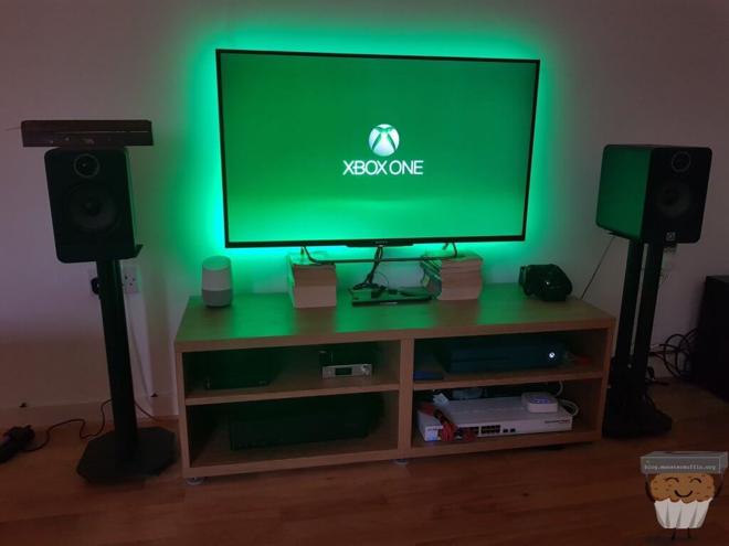
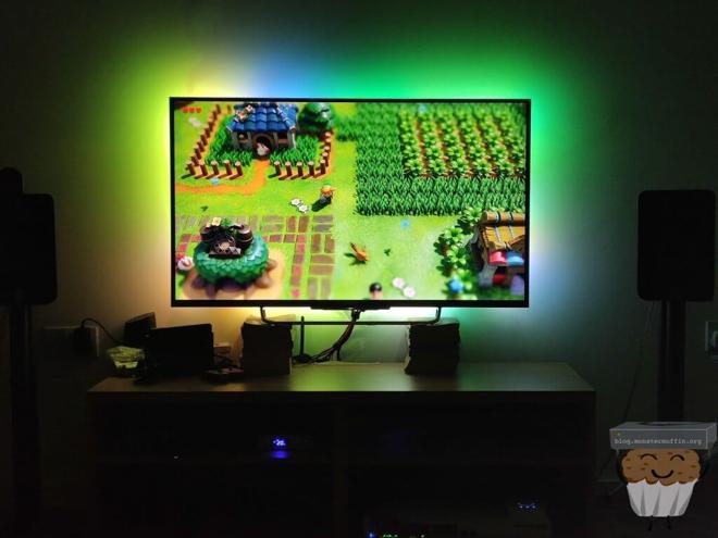
So, if you want something like the below, then continue reading….
Note #
Usually, when I do things like this, I do the blog post at the same time as the project, however, because I am very lazy and never actually finished this blog post when I initially set this up, I am now blogging about this 3 years after I completed the project. I’ve decided to rewrite this post and actually finish it as I am once again doing this on another TV. Some of the parts I originally used are no longer available so substitutes have been made, you may also have to do the same.
My girlfriend and I are currently turning one of the buildings in the garden into a den of sorts. After looking for a short time I managed to snag this 55" KD55X8509C for £200 which in my opinion was a pretty banging deal.
One major caveat #
As with the title, this solution will only work for HDMI devices, meaning, this will not work for your TVs native UI. If you use the smart UI built into your TV, this just will not work. This has never been an issue for me as I really, really hate 99% of software baked into the OS of TVs. Most of them are slow and limited, and even when it’s something decent like Android TV the SoC lets it down, there are a few exceptions to this of course, our KD-85XG9505 is simply amazing, but for over £4k you’d hope so… But I digress.
Shit you’ll need #
So here is a list of what you will need for this project, some of the items aren’t really needed but makes life a lot easier. I’ll go ahead and make a quick list below and explain below that what each does. I’ll be adding UK Amazon links because, well, I live in the UK, (unfortunately). You should be able to get identical or similar items wherever you’re located from wherever you chose.
You may need more things depending on how you decide to go about your setup, but the below should have you pretty much sorted. I’m going to assume you have things like HDMI cables…
| Item | Price | Amazon Links |
| Raspberry Pi Zero W (Or other) | £33.20 | Linky |
| Official Raspberry Pi Zero Case | £5.41 | Linky |
| SanDisk Ultra 16GB microSDHC Memory Card | £5.99 | Linky |
| HDMI Splitter 2 Way Hdmi Splitter | £11.95 | Linky |
| 5V/3A Power Supply Adapter | £6.69 | Linky |
| LogiLink USB 2.0 Video Adapter | £14.40 | Linky |
| MENGCORE® 5m 16.4FT 150led WS2812B | £18.99 | Linky |
| Multicolored Dupont Wire | £5.95 | Linky |
| FiveHome 5 Port HDMI Switcher | £36.99 | Linky |
| HDMI to RCA | £9.79 | Linky |
| Male to Male RCA Coupler | £6.59 | Linky |
| 100 Ohm Resistor | £1.69 | Linky |
Optional configurations
If you’re using one source and don’t care about other devices, you can just forgo the HDMI switch, you can always add this in later.
Also, if you’re using a small TV with a small number of LEDs you could opt to power the LEDs from the Pi’s own +5v power supply on the GPIO. I would do some research into what’s a ‘safe’ number of LEDs to do this with though.
Some, if not all of the above items can be sourced cheaper elsewhere. The Pi, for example, can be had for under half the price but I am just leaving an Amazon link for ease. Lockdown has inflated the price of all hobby items!
I’m just going to dive into my parts bins and see which Pi I pull out, but you can feel free to use whatever is cheapest/you have/you fancy. If buying a Pi Zero however you will need to solder on the GPIO header if not already on.
How this is going to work #
The way this will work is the following:
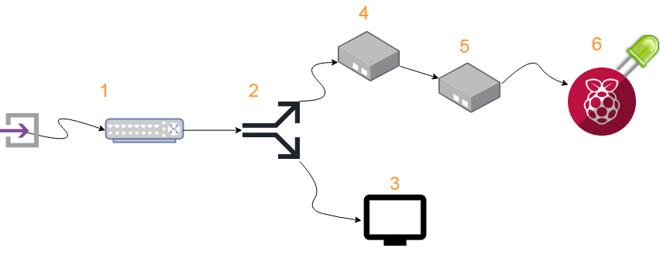
- Any HDMI input device you wish to Ambilight is plugged into a HDMI switch, ideally one that auto switches.
- A HDMI splitter is employed to send one signal to the TV, and one to our AmbiPi setup.
- TV receives signal as it normally would on your preferred input.
- A HDMI to AV converter converts the digital signal to an analogue one to be used by the Pi.
- A USB grabber takes the analogue signal from the converter and allows the Pi to view this via USB.
- Hyperion uses this captured video stream to work its magic and output PWM to the LEDs based on the input.
I use a HDMI switch at the start as it allows anything that’s plugged into that switch to be Ambilightable, you can of course completely omit this if you only care about one source, I just think it looks pretty sweet with gaming hardware!
To box or not to box? #
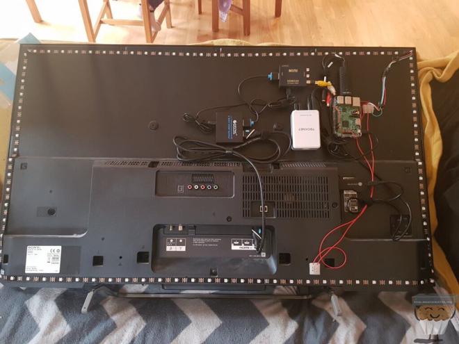
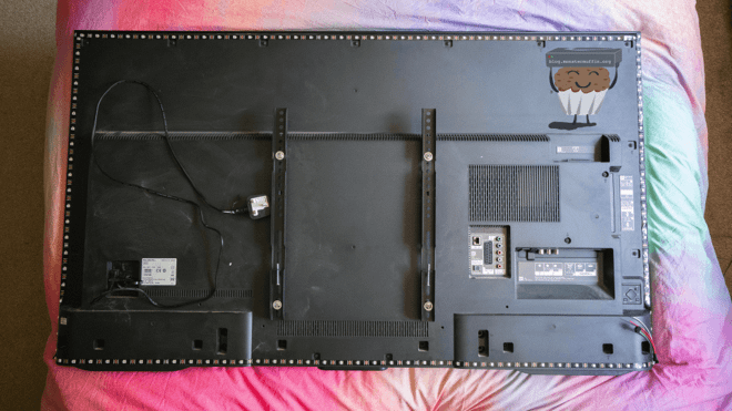
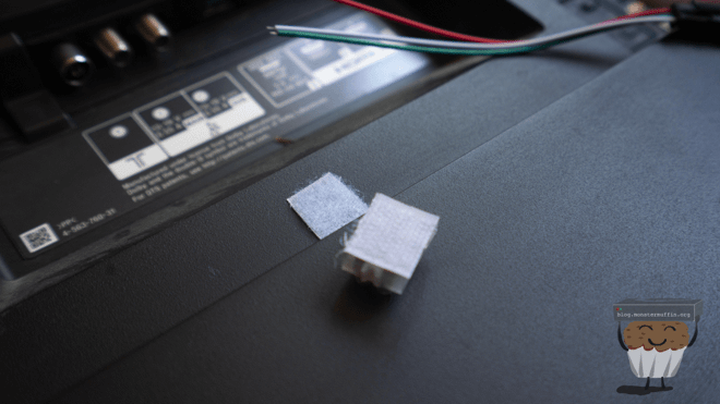
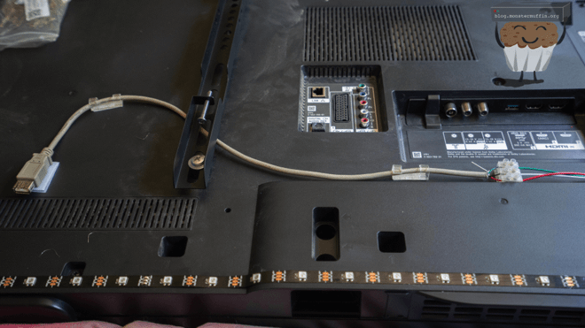
Now, when I previously did this (above images), I used velcro to mount all the parts on the back of the TV. This has worked well, and it’s not a big deal as this is very much ‘set it and forget it’, but it did make moving the TV a bit of a pain in the ass when we moved out.
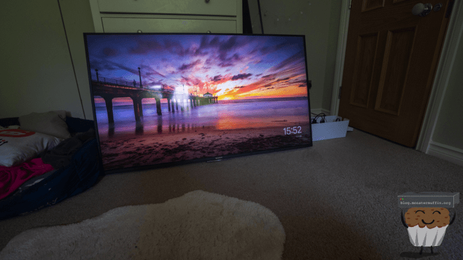
This time, I will be putting everything in a project box and just running the wires from the LEDs into said box to make life a little easier down the road. Do whichever you prefer. Below is a picture of how it’s mounted to my bedroom TV.
I used Raspbian lite for this as the Pi is much older and, well, there’s not much need for much else.
The Pi stuff #
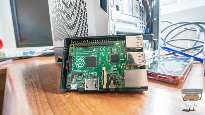
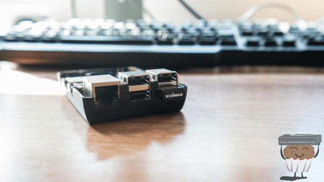
I’m using the first Pi I found in my stocks, which is this old Pi Model B+. Use anything you want, a Pi Zero would be great for this but if you have older models laying around like me this is perfect.
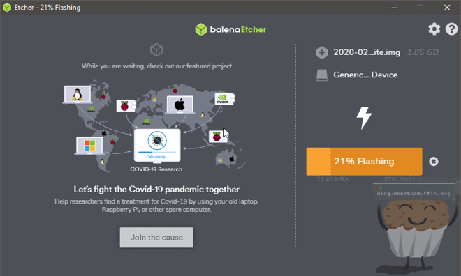
First thing you’re going to want to do is nab yourself a copy of Raspbian from here and flash it with whatever software you choose, balenaEtcher is pretty good.
Now we setup the SD card so that the Pi can connect to our WiFi network when it boots first time, as well as SSH being enabled. You should have 2 new partitions on mounted on your machine after the flashing is complete, one of these ‘BOOT’ should be writable, head there and:
Run Notepad
In a new file put in one space and nothing more
Click File / Save As …
Be sure to set Save as type to All Files (so the file is NOT saved with a .txt extension)
Call the file ssh and save it
Close the file
Alternatively, just create a file with no extension called ssh.
And for WiFi, create a file in the root of boot called: wpa_supplicant.conf with the following config:
country=GB
ctrl_interface=DIR=/var/run/wpa_supplicant GROUP=netdev
update_config=1

network={
    ssid="<NETWORK-NAME>"
    psk="<NETWORK-PASSWORD>"
}
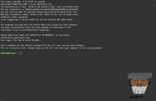
Slap that SD into the Pi, plug it in and check your DHCP server/do a network scan to find out it’s IP, and connect to it via SSH with the default Raspian credentials of pi:raspberry.
If you’re able to do this congratulations! We’re ready for the next step of configuration which will come after plugging everything in below. For now, you can power down the Pi and follow along.
The LEDs #
The first thing to do is the get the LEDs around the TV. There are several ways of doing this, the proper way, the kinda proper way, and the way I do it.
Proper way: Soldering the connections is really what you should be doing, but honestly I have neither the time nor patience for this. If you want to make sure your setup is rocksolid though, this would be the way to go, I suppose
Here’s how it should look if done this way, done by my pal over at Tig’s blog.
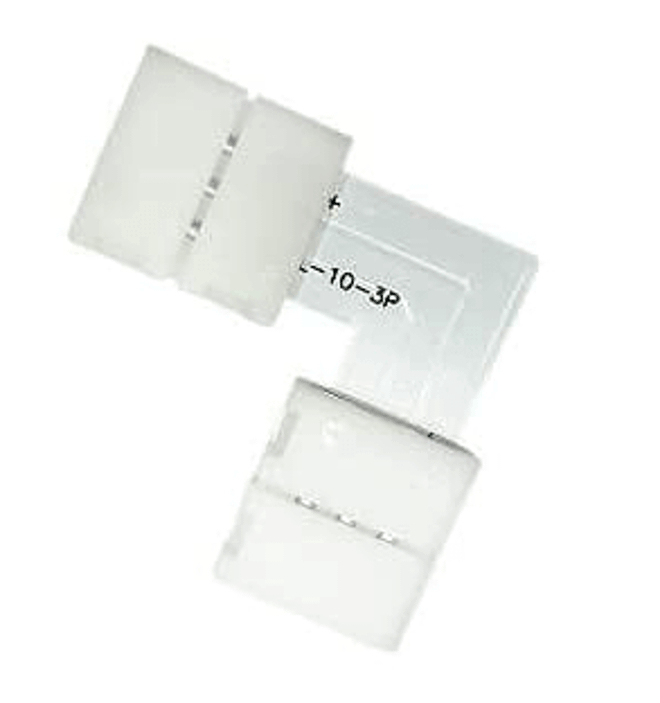
The kinda proper way: You can cut the LEDs that you need and use LED right angle joiners to connect them together. So, I did try to do this the first time I did this whole thing and they just didn’t work well for me. The fitting was a nightmare, the pins on the connector were shit, and the connection was always having issues. I’m only saying this is a kinda proper way as most things I’ve read seem to be success stories and this is generally how I’ve seen it done, maybe I’m just an idiot.
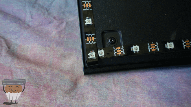
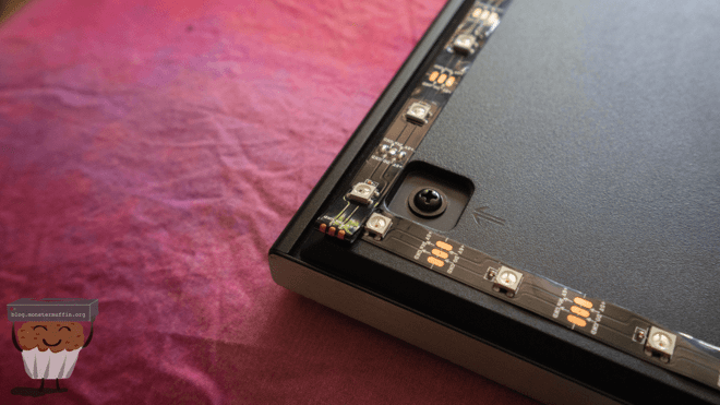
The way I do it: Just bend the cunts. Honestly, I see no reason to do anything else, this method works exceedingly well, is the easiest and has yet to fail me after doing this multiple times, and it’s been a few years now. It allows you to have the maximum amount of LEDs on the back of your TV, it can be done quickly. As long as you’re careful I’ve done no damage to any of my strips yet!
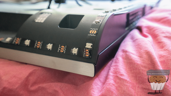
So, go ahead and put the LEDs on your TV, making sure to put the connector side somewhere convenient. Try and ensure there are the same number of LEDs on all sides, this proved quite difficult as the TV I am doing for this tutorial is bulky towards the bottom, but I managed it.
Putting a different number of LEDs won’t be the end of the world, I actually fucked this up the first time I did it but for best results, do your best.
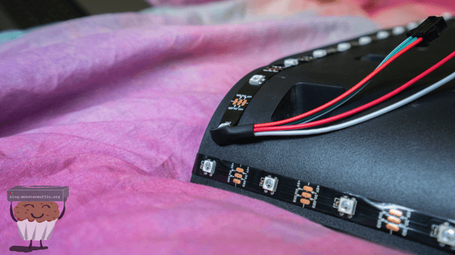
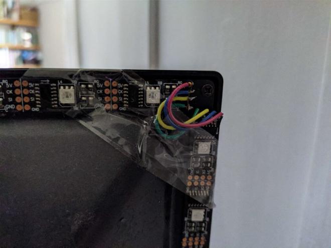
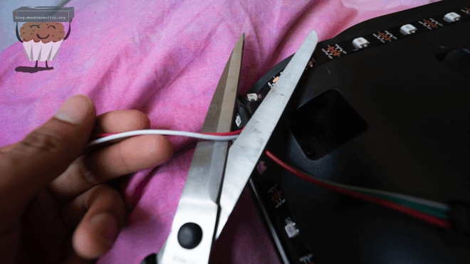
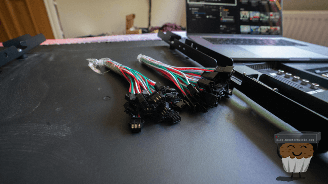
Go ahead and cut off these two wires, we don’t really need these. If you’re running an insane number of LEDs you might want to wire these to the end of the strip.
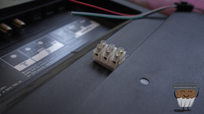
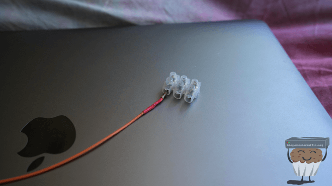
Next up I velcro’d some connector blocks to the TV and fed the LED wires into here.
I spliced a USB extension cable and connected one end up as seen here. This gives me the ability to move the setup quickly when needs be. I used LED connectors that I got a pack of for cheap on Amazon.
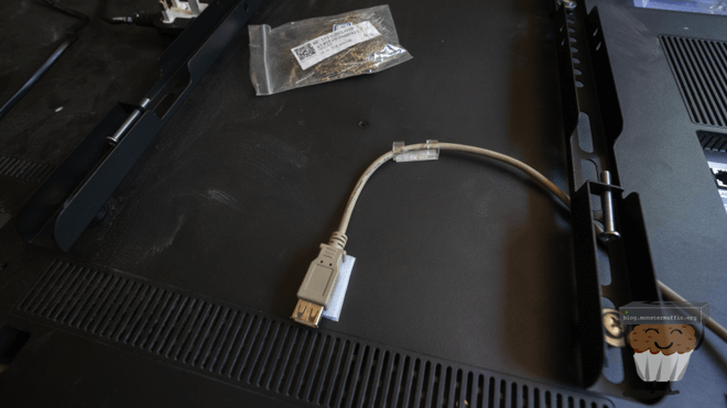
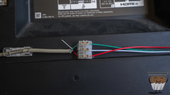
The TV aspect of things is now finished and we have a nice USB interface to connect it all up to, you can of course hardwire this in.
Connecting everything together #
Now we connect all the bits together, and then we will return to the Pi.
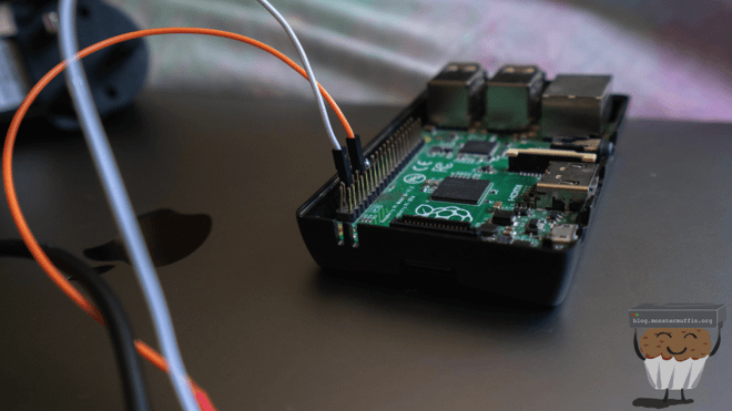
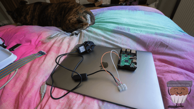
Now we connect the Pi to the LED strip along with the power strip. We connect this as the below image illustrates.
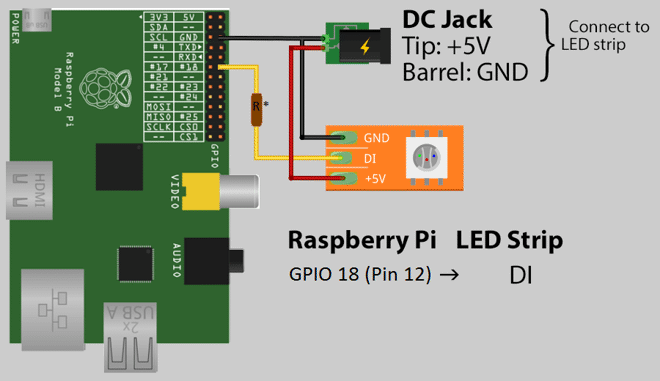
https://hyperion-project.org/wiki/3-Wire-PWM
Ensure the PWM signal wire connection from the LEDs is connected to GPIO18 which is pin 12 on the Pi, with the 100 Ohm resistor in between as above. Connect ground to both ground on the PSU and on the Pi via pin 6. Finally, connect +5v on the LED strip to the PSU +5v.
If you decided to use the Pi’s +v5 for your LEDs, connect it to either pin 2 or pin 4.

https://www.raspberrypi-spy.co.uk/2012/06/simple-guide-to-the-rpi-gpio-header-and-pins
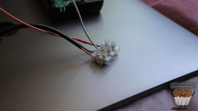
Here is how I’ve connected everything up.
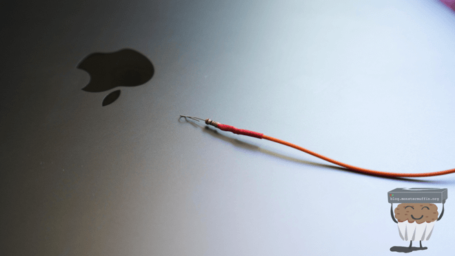
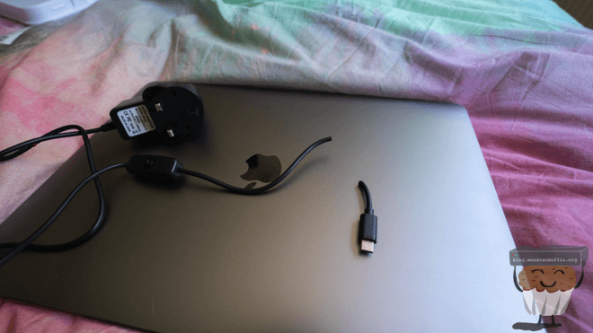
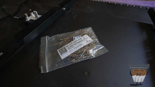
I soldered the resistor to one end of the PWM cable going to the Pi and then heatshrunk it. I cut the end from the PSU I ordered which was for a Pi 4, and connected it all up to the block.
The first time I did this I was made to buy 400, so I have loads of these things. If you’re in the UK and want a few for free, PM me on Discord or something.
With that all done, it’s time to box everything up, or arrange it on the back of your TV if you’ve chosen that route.
Below is how everything should be connecting, leaving out the power for now. In testing I will be using a Chromecast connected through the switch, when this goes up I’ll be using an Nvidia Shield.
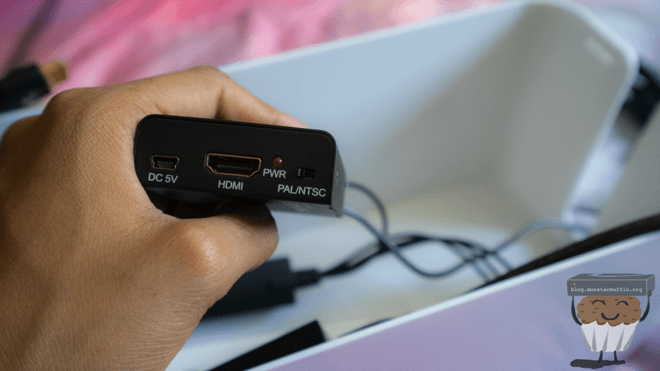
One thing to ensure at this stage is that you are using the correct PAL/NTSC setting on the converter else you will face issues and not know what’s wrong.
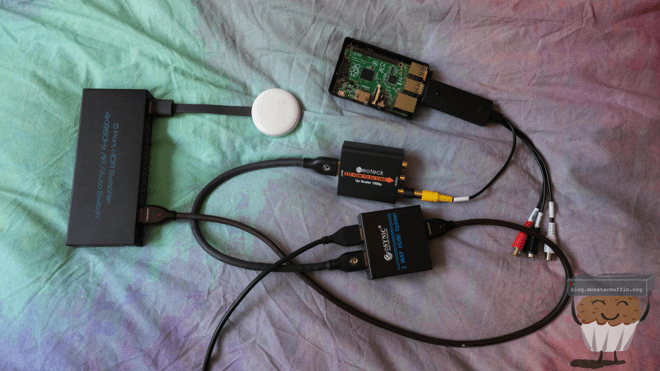
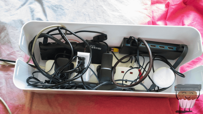
Below is everything in the box, this will be prettied up once it goes into production, but for now this should suffice. I’ve used a cable tidy box which allows me to route the power cable and USB cable out one end, and the HDMI cables from the devices to be ambilight’d from the other.
Once it’s all powered on you should see that source is displaying on the TV, which is a good first step, and the Pi should be accessible over SSH, as well as all the other devices powered up too.
Back to the Pi #
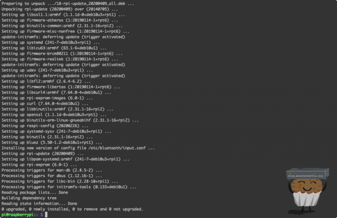
Let’s do an update on the Pi to get everything up to date.
sudo apt update; sudo apt upgrade -y; sudo apt autoremove -y
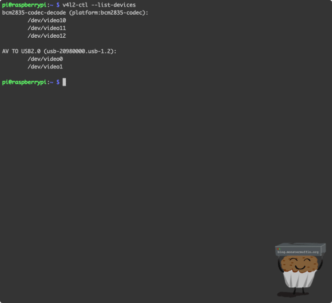
If you haven’t already made sure that your USB video grabber is working/compatible, check now using the following command:
v4l2-ctl --list-devices
As you can see here I have an AV TO USB2.0 device, which is the video grabber.
Now we will install Hyperion, you can do this via the client configuration application that we’ll use to configure Hyperion in a second, but we will do this via the terminal instead.
curl -k -L --output install_hyperion.sh --get https://raw.githubusercontent.com/hyperion-project/hyperion/master/bin/install_hyperion.sh

chmod +x install_hyperion.sh

sudo sh ./install_hyperion.sh
You might see the following, which is good. We didn’t do this manually as the installer does this. Press Y when asked to reboot.
Please reboot your Raspberry Pi, we inserted dtparam=spi=on to /boot/config.txt
Now we will use Hypercon to configure the Ambilight setup. Get the latest Hypercon version from here, and open it up on your machine.
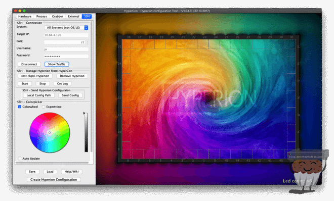
Head over to SSH in Hypercon, enter your Pi SSH credentials and connect as below, you will see this turn to Disconnect if this is successful.
Head over to the Hardware tab and give your configuration a name, these settings are my personal settings, feel free to tinker to your liking.
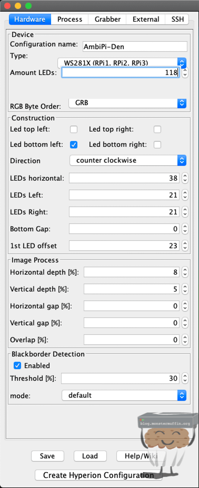
- Change the type to WS281X.
- Change RGB Byte Order to GRB.
- Configure the number of LEDs you have under ‘construction’.
- Configure where your LEDs start, and which direction they go in.
- Enable Blackborder Detection and change to 30%.
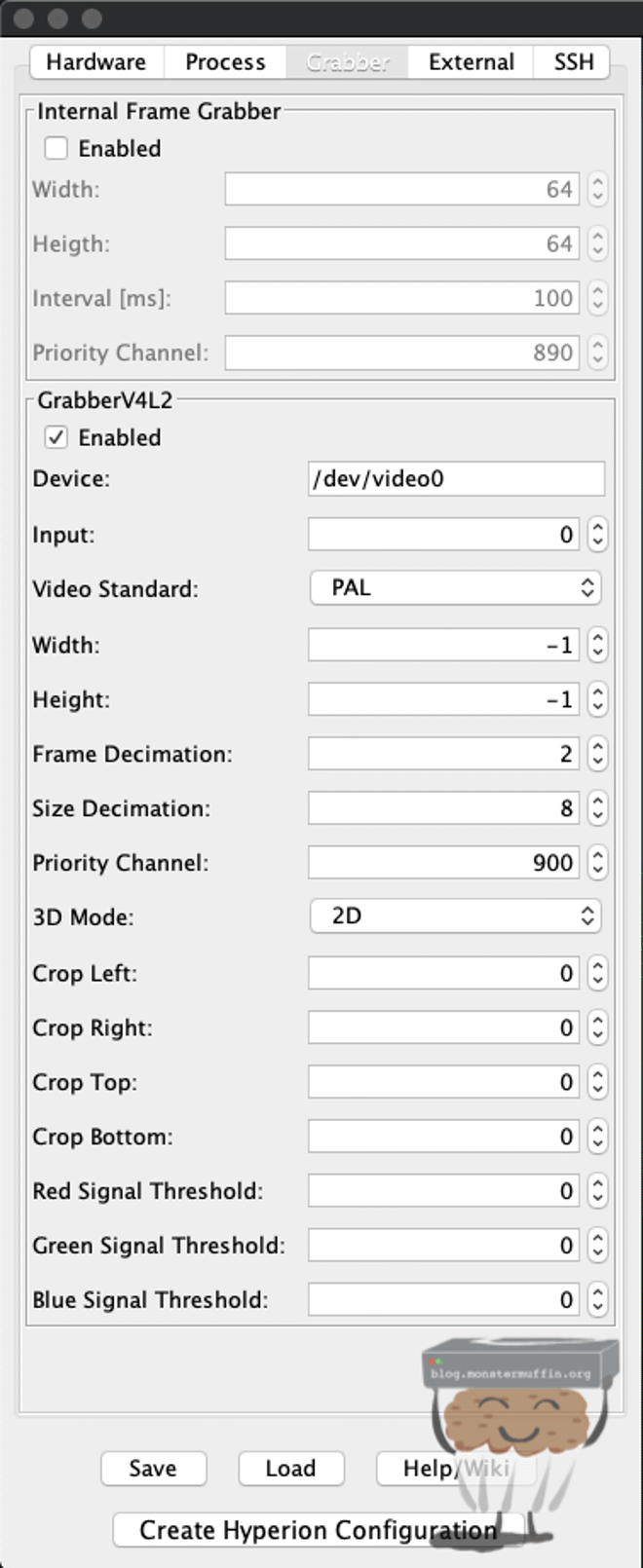
Leave Process alone, and head over to grabber. Disable Internal Frame Grabber and enable GrabberV4L2, and leave the rest as default.
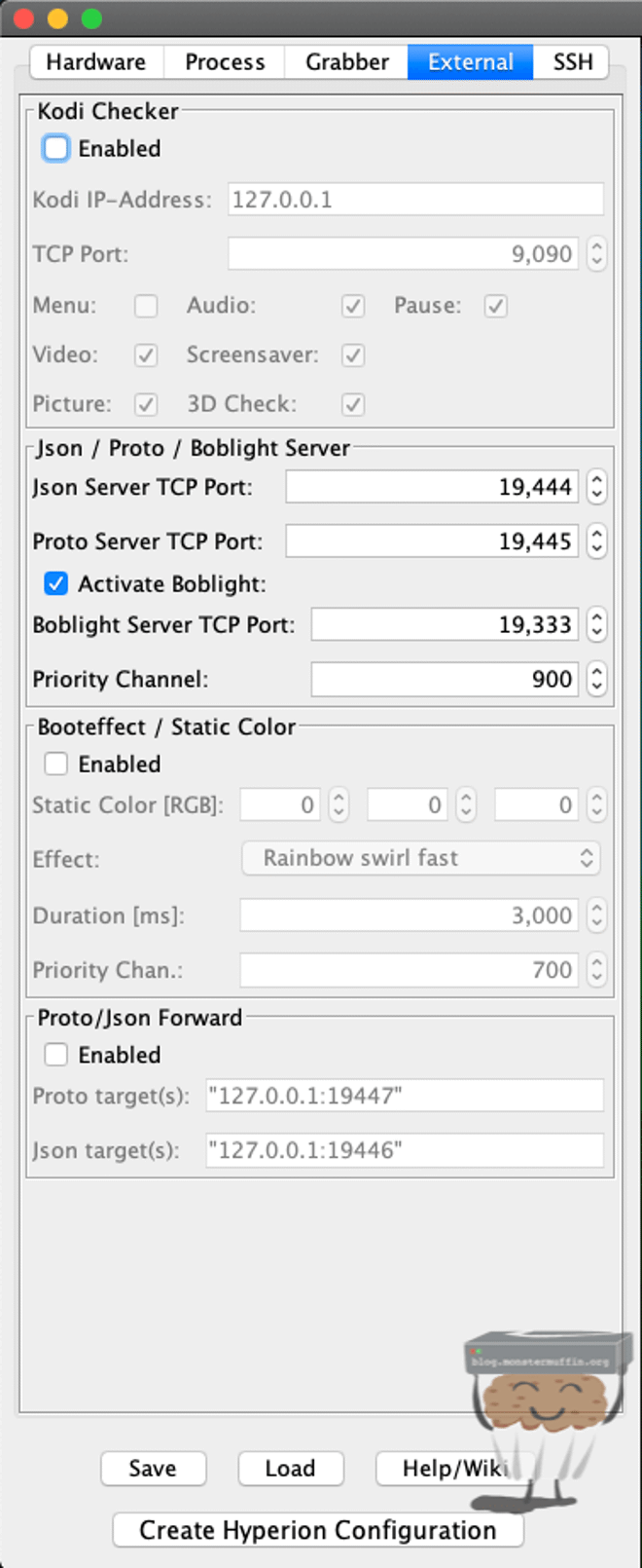
Next in External, activate Boblight and disable the booteffect, I find this annoying but you’re welcome to leave this enabled.
Finally, back in SSH, ensure you’re still connected and click on ‘Create Hyperion Configuration’. Create the config, then click on ‘Send Config’.
Your config will be scp’d over to the Pi.
At this stage, you should be able to right-click the preview window on the right and click on ‘Take grabber screenshot’. This should result in a snap from your source input, if it doesn’t recheck wires and connectivity. *I had issues with this, see note below.

If you can see something like the above, then you should be good to go. Start Hyperion using terminal or click start in Hypercon and boom! You should have sweet sweet Ambilight.
Note: I was having a lot of trouble with Hyperion starting at first, this turned out to be a shitty grabber. Even though it was showing up it did not work with Hyperion. I ended up grabbing one of the working grabbers from another setup and that worked fine, so I knew this one was shitty. I couldn’t get a screengrab in Hypercon, so if you have the same issue, change grabber.
The Logilink one I have linked in the parts list is the one I have used with success many times before, but is unfortunately out of stock right now, when I find a replacement that works well I will change the link and update this paragarph.
You did it! #
And that’s all there is to it really, from now on it’s pretty much set it and forget it. I’ve been rocking my main one for over 3 years now and never needed to touch the config or the Pi, it’s worked flawlessly.
Turning it off can be a bit annoying, how we used to do it is just turn the plug on and off whenever we turned the TV off, but there are many ways of doing this with automation.
You can put an IoT plug on the LED PSU and have that controllable via Google/Alexa or automation when the TV/source is on.
Another option that a buddy of mine decided to do was to add it into Homeassistant via scripts, so when the TV turned on, Hyperion was started, and when the TV was switched off Hyperion was shutdown, this will kill the LEDs. This is what I am moving towards going forward as everything is IoT connected anyway.
Unfortunately, I do want to release this blog post before I mount the TV in the den, so for now, here is a little clip of it working on my bedroom TV instead of the above TV being on the floor.
